Basement Build #5: Killswitch

Hello and welcome back to another installment of Basement Builds! I apologize for the long hiatus, I got real busy starting a new job and putting together a band. Most of my effort lately has gone towards writing new music so the tinkering has taken a real backseat. However, as I was working on a riff for a our newest song, I noticed the tone knob on my primary axe was coming loose. This wouldn’t be such an issue had I not just tightened this tone knob so I decided enough was enough and this pot had to go. Time to stop talking about my favorite guitarists and start playing like them.

Step 0: Decide You Need A Killswitch

20200409_153608

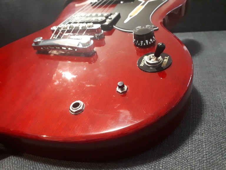
A loose knob that has got to go.

This is the easiest step of the whole build. I still remember the first time I heard Tom Morello’s guitar solo in Bulls On Parade. I was so blown away that I started experimenting with the toggle switch on my own Univox Les Paul copy. Being a pretty cheap starter guitar I broke the toggle switch almost instantly by violently throwing it back and forth. I then asked my dad to help me wire a killswitch into an old patch cable and in that moment my whole life changed. I became much more excited about the guitar knowing that I could do these mods myself to completely change the instrument. I think it was that moment that sealed my fate and lead my to pursue a degree in engineering but that’s not important right now. We are here to talk about how to wire your own killswitch which brings my to step 1.

Step 1: Remove Tone Knob (optional)

I have labeled this step as optional because you do not have to remove the tone knob to add a killswitch. If you want to drill an additional hole in the body of your guitar and put the killswitch in that hole, by all means go for it. I don’t really use the tone knob on this guitar though and didn’t want to do any drilling so am using the existing hole.

This slideshow requires JavaScript.

The tone knob is quite easy to remove. Simply pull the knob off the shaft and the remove the nut and washer. The remaining part of the tone knob (the potentiometer) may fall into the body of the guitar but that is okay. we will be opening the back in just a minute to get that out.

Finally, take the back panel off your guitar, pull the potentiomenter out of the whole, put the nut and washer you removed back on for safe keeping and use a dab of glue to secure the potentiometer out of the way. The potentiometer can be removed entirely if you are good with wiring but this is a very risky move and could end up costing you a lot if mess up and have to get something repaired.

Step 2: Add Button

20200409_160928

Secure the button tighter than the knob

Once the tone know is removed and out of the way we add a button to the hole that is now vacant. I used a little bit of Loctite and some pliers to make sure the button would not come loose like my tone knob did. It is very important that you use a normally open momentary switch. Any other type of switch will have to be wired differently. Normally open means that current will not pass through the switch until the button is pressed. Momentary means the switch will not ‘lock’ into place when the button is pressed like a guitar pedal would. Here I should have included sketches of my circuit but I did not plan this build out like my others. This was an impulse build that I did out of frustration towards the loose tone knob. I do not recommend winging your guitar mods unless you also have a degree in engineering but if you also have a degree in engineering then you already know better than to go about projects without a plan.

Step 3: Wire Button

20200409_165047

b.eng not required but recommended

Once the button is securely in place, you will need to wire it up. This is where it is important to know what kind of switch you have. Since I have a normally open switch I had to wire it in a way that would not effect the signal passing through the guitar until the button was pressed down. To do this, I connected the two leads on the button to the two terminals of the input jack. When the button is not being pressed the two terminals of the input jack are not connected and the signal will pass through the electronics of the guitar as it normally would. When the button is pressed it will create a short between the two terminals of the input jack creating a path of less resistance. Now given the option of passing through the button or passing through all of the guitar’s electronics, the signal will choose the button thereby ‘killing’ the guitar. I put a little but of red electrical tape over one of the terminals of the button so there would be no chance of the two leads touching each other and turning my switch into an always-closed instead of normally-open.

Step 4: Rock Like Your Heroes

Now that your kill switch is wired up you can put the back panel back on and rock out like your favorite killswitch-using guitarists. Leave a comment and let me know who inspired YOU to install a killswitch.

Basement Build #4: Briefcase Boombox 2 (Bluetooth)

Hello and welcome back to another installment of Basement Builds! I am very excited for this one and have been thinking about it since my last build. As promised, this model of the Briefcase Boombox is Bluetooth and rechargeable. After all the positive feedback from my friends and family on the last build I though these would make great gifts for the upcoming holiday season and headed straight for the thrift store to start this project.

WHAT YOU’LL NEED:

2018-12-10B Square

  • Thrift Store Speaker Cabinet
  • Sketches and plans
  • Disassembled Bluetooth Speaker
  • Screwdriver
  • Drill
  • Scissors
  • Soldering Equipment
  • Saw
  • Pencil
  • Breadboard
  • Measuring Device
  • Thrift Store Briefcase

Step 0: Obtain Better Speaker Cones

Step0_1

Removing the protective screen to access the speaker cones

The two main goals for this project are a real vintage look at a real low cost so the thrift store is where we should look for most of our parts. I was able to find both a speaker cabinet and a briefcase for under $5 at my local Value Village which make up most of the final product. What I couldn’t find was a Bluetooth speaker but sometimes these come as promotional item in cases of beer so check out your local liquor store for that one.

Step0_2

Removing the speaker cones

Unfortunately no companies were running such promotions at the time of this build so I had to go to an electronics store. You don’t need anything fancy because a large part of the sound quality comes not from the internal wiring but the speaker cones which we will be replacing. Much of the cost comes from the casing which we will be replacing as well so I picked up the cheapest Bluetooth speaker I could find which also happened to be around $5.


20181105_150016

Internal wiring of the speaker cabinet

Disassembly of the speaker cabinet was quite easy as we can see through the picture gallery. This particular unit has a protective screen that popped off very easily and the cones just unscrewed out of the cabinet. Pay attention to the internal wiring of the cabinet as we will want to try and match this in our briefcase. My cabinet had the two cones in parallel with a resistor and capacitor before the tweeter (smaller cone).


Step 1: Disassemble Bluetooth Speaker

Step1_1

Circuit board from Bluetooth speaker

Once your speaker cabinet is all apart it is time to tear open that Bluetooth speaker. All Bluetooth speakers are different so I can’t offer much guidance here but once apart they ought to all be fairly similar. Inside should be a circuit board with lots of surface mount components that you don’t really need to worry yourself with. All you will need to do is take the two wires attached to the speaker and disconnect them. Try to leave yourself a bit of wire to work with as it is easier to solder wire to wire than wire to circuit board. In my Bluetooth speaker there was a red and black pair leading to the battery and a red and blue pair leading to the speaker. I just cut these red and blue wires and pulled everything else out of the casing to test.


Step 1.5: Test Circuit with Your New Cones (recommended)

Step1_2

Testing in progress

I think it’s a great idea to test things out before getting to far in to make sure things are going to work the way you think they are so if you’ve got a breadboard I highly recommend testing. You’ll want to take the positive (+, often red) and negative (-, often blue or black) leads and connect them to the same node as the positive and negative leads from your speaker cones; this is called connecting them in parallel. Series would be if we connected the leads from positive (+) leads on one speaker cone to negative (-) leads on the next. This has its own advantages which you can read about here and wire this circuit however you like. The great thing about a breadboard is you can quickly try both ways and hear the difference yourself!


Step 2: Prepare Your Briefcase

Step2_1

Circles printed to match the size of the speaker cones

Step2_2

Uh oh! This is why we measure twice

Be sure to plan this out. The last thing you want is a bigger hole than you need which will compromise the structural integrity of the briefcase face.  We can see in my picture that I measured wrong the first time and had to print a new sheet of paper so the speaker would fit better. This is where measuring twice can really save your ass. Once with the ruler and once with the template.

Step2_3

Layout planning

20181208_135231

First cut

I then used the circles cut out to see what the boombox would look like when complete. Once happy with the layout go ahead and cut out those hole.

Step 3: Affix the Speakers

20181208_154915

Speakers in place

Here I drilled the speaker cones directly into my briefcase wall with the originals screws in the speakers as I felt the briefcase is sturdy enough but you may want to reinforce this with a thin sheet or particle board or more cardboard if you don’t trust your briefcase. Get ready to do some sanding as I recommend cutting the hole on the smaller side and sanding to fit.

Step 4: Mount Your Circuit Board

Step4

LED board mounted over a little window to shine through

In my picture I have not yet put the circuit board in but I just attached it with a little hot glue right onto the inside of the case. Pictured left is an LED board that came from my Bluetooth speaker I wanted to integrate. Little straps of leather salvaged from the lining helped us get it in the perfect spot. Not all Bluetooth speakers will come with lights so this step is going to vary from build to build. Feel free to get a little creative here with your wiring and use the space inside of the case here to your advantage.


Step 5: Wire It All Up

Step5_2

Cover up that bare metal

Step5

Solder connections for a more durable build

With everything in place all that’s left is to solder all the connections for the speakers you swapped out. A little sketch of your circuit around your workspace can be very helpful. A set of helping hands can be extra helpful here. My girlfriend gave me this set for my birthday as she got tired of being my set of helping hands. It’s a good idea to wrap your connections in electrical tape once cooled to prevent shorts.


Step 6: Clean It Up

20181208_154934

Almost finished

That’s it! You’re pretty much finished. All that’s left is to clean up your build a little bit, maybe taping down your wires and adding finishing touches to the outside. We didn’t put any controls on the outside of this unit because it’s Bluetooth so you’ll have to open the lid to turn it on but after that it’s all from your phone.


Complete

Finished product (photo courtesy of the wonderful Emily Fitzowich)

P.S. Why Buy Gifts When You Can Thrift Gifts?

These Bluetooth boomboxes get a lot of attention and will make great gifts this holiday season. And if you’ve got to travel I can tell you they definitely fit in overhead bins no problem and can start over a dozen conversations on only two plane rides.

Basement Builds #3: Briefcase Boombox Prototype 1

Hello and welcome back to another installment of Basement Builds. I apologize for the long hiatus but it turns out moving across the country can be quite an ordeal. Now that things are settled I am back at it again with another exciting build for you! I call this one the Briefcase Boombox and it has been by far my favourite project. I got a little excited while working so I may not have all the best pictures of the progress; but worry not, there will be more iterations of this project. I am planning the next Briefcase Boombox to be rechargeable with Bluetooth capabilities, and the one after that to function as a Guitar Amplifier.

To begin I would like to briefly explain the motivation behind the first prototype of the Briefcase Boombox. If you’re anything of an audiophile like me you likely got yourself into record collecting with everyone’s first record player, the Crosley Cruiser Delux Portable Turntable, only to realize that the superior sound quality of vinyl is negated by the Crosley’s tiny tweeters. Upon realizing that the built-in speakers are completely useless you went out and bought a better record player and now have this Crosley collecting dust. Well I have great news for you! The crappy Crosley portable turntable can be upcycled into a super cool Briefcase Boombox that will have all your friends jealous of your dope décor.

WHAT YOU’LL NEED:

  • Crosley Cruiser Deluxe Portable Turntable that you regret buying
  • Speaker cabinet that is unnecessarily large with cones you can remove
  • Soldering equipment (Check out the Links tab for help soldering)
  • Drill
  • Handsaw

Step 0: Obtain a Better Speaker Cone

20181026_171619

Speaker Cabinet; Mid Operation

20181026_164609

à la VV Boutique (Value Vilage)

I’ve had the idea for this project for some time but no real way to execute it until I went Halloween costume shopping at the Value Village. There I found an old cabinet speaker for only $4 and that seemed like a good deal to me. Praying that the speaker cones were still functional I bought this thing and brought it home to tear apart. For this build all I ended up using was the main speaker but I kept the tweeter and all the wires as well to use on future builds.

20181028_135747

Cabinet Haul; Tweeter is in a bag to keep the parts together (the apparent sub was fake).

Step 1: Remove the Turntable

Crosley Labeled

Crosley Deluxe Guts

The first step was taking apart the Crosley to understand how it works and which parts can be reused. Once you’ve got the top off I would recommend holding on to it as most of those parts can be used in case your main turntable has any problems. Underneath the hood we can see how everything is connected and it is fairly clear what each of those connections are doing. Given that we are removing the turntable aspect of this case we can also remove the wires attached to it to clean things up a little.

Step 2: Remove Volume Control Board

20181031_131858.jpg

Take what you can; give nothing back

We are going to want the circuit board with the volume knob on it so make sure not to disconnect any of those wires. This board is just glued down so it can be removed with a bit of care. To make things easier on myself I used a small handsaw to cut the section of wood that that board is attached to out but this is optional. In the image to the left I have also disconnected one of the tweeters because my original plan was to put the volume control in its place but that didn’t fit as well as I was hoping so the design changed. If you look closely you can also see a set of wires that are not attached to anything. These came from the Vinyl Input/Headphones Out. Hold on to these wires as they may be useful later.

Step 3: Cut a Hole

20181031_121915

Marked for Extraction

With the case mostly empty I felt I could now safely cut the hole in the lid without damaging any of the good stuff inside. Be sure to measure twice and cut once so that you’ll have enough lid left to screw the speaker cone directly into the case. I made the hole by drilling a series of holes around the inside of my marking, connecting these holes with a small handsaw, and then sanding the edge until the speaker cone fit snugly. I recommend cutting a smaller hole than needed and sanding to size but you can cut to size if you’d like to skip the sanding. Just be careful not to cut too big.

Step 4: Affix the Speaker

20181031_131903

Old Cone in a New Home

The box that the Crosley turntable comes in is thankfully sturdy enough to screw directly into without any reinforcement. Here I have the new speaker facing outwards so that the Boombox works best with the lid closed but you can have your speaker facing inward if you’d like. In fact, if you have the speaker facing inward there should be enough room left in the box that you can leave the record player aspect functional. Stay tuned for that basement build if I ever get my hands on another Crosley Cruiser Deluxe Portable Turntable.

Step 5: Wire the New Speaker

20181031_155753

Don’t Miss the Mark; RED is +

Now that the speaker is in place it needs to be wired. There are two options here and you can take your pick. You can either use the main speaker to replace one of the tweeters or wire the main speaker in parallel with one of the tweeters. I took the leads off one of the tweeters to connect the main speaker but will likely reattach the tweeter I removed later. This may sound funny if your music is in stereo but I feel as though the majority of music these days is mono. To overcome the issue where the left channel is much louder than the right (or vice-versa) you can wire all three speakers in parallel.

Step 6: Reattach the Volume Control

20181031_161037

Measure Three Times For This One

Now that everything is wired we need to put our volume knob on the outside. To do this simply drill a hole in the lid and affix the knob. You’re now done and can rock out to your super cool new Briefcase Boombox!

P11402872

Looks Great; Sounds Better

Basement Builds #2: Distortion Guitar Pedal

Hello and welcome back to Basement Builds! In this installment, I will be showing you how to make your very own Distortion Guitar Pedal. I like to call this pedal The Stephen Hawk ROCKing Pedal (may he rest in peace) because it’ll kick your tone into high gear and have you tearing through the fabric of space and time. Sim_waveformI have designed this pedal to be as simple as possible with very few parts so you don’t need to be a world-class physicist to put it together.

Step 0: Gather Required Materials

20180316_204009
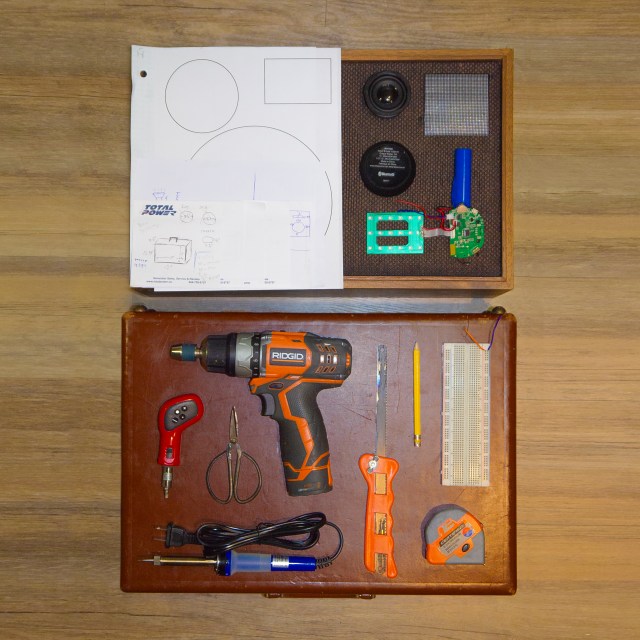
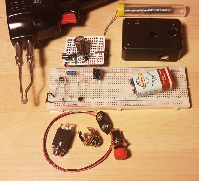
The first thing you will need to do is gather your parts. As with the microphone, most of these parts can be found in your home but I will try to link as much as possible to be safe.

Resistors and capacitors have a large effect on the circuit’s output so it is important to choose carefully. The transistor and diodes are also crucial to the pedal’s performance but any NPN BJT and regular diodes will work fine. I handpicked all of my values to produce my own unique tone but if you can’t find the same values I also used ADS to simulate the circuit and found a good range for each component.

Part Min Mine Max
C1 0.1 uF 4.7 uF 100 uF
C2 1 uF 1 uF 100 uF
R1 1 kOhm 9.84 kOhm 20 kOhm
R2 2 kOhm 98.2 kOhm 1 MOhm
R3 1 kOhm 98.4 kOhm 1 MOhm

For R1 you should try to stay as close to 10 k as possible. C2 and R3 are much less important as long as you stay within my range. C1 and R2 are where this gets exciting. C1 is used primarily to block the DC voltage from going back into your guitar but it also has some control over the tone. A lower value for this capacitor cuts more bass so keep that in mind when choosing your cap. This could also be replaced with a variable capacitor to give your pedal a tone knob. R2 is used to bias the transistor which controls the gain of the pedal. More resistance here leads to more gain at the output. A variable resistor, or potentiometer, here can act as a volume knob.

 Step 1: Plan Your Layout

Before you begin soldering any connections it is very important to plan how you are going to construct your circuit. Every breadboard/perfboard is different so I can’t tell you exactly how to hook it up but I do have some guidelines.

I like to start by looking at the full circuit diagram and labeling nodes. A node is where two or more components meet. In the figure below I have labeled the nodes RAIL, IN, BASE, COLLECTOR, and OUT. Since there are five nodes, there will be five points of connection to consider.

Schematic

Perfboard_2

I then count the number of connections on each node to see how they will fit on my board. We can see that node OUT has four components, five including the jack not shown on the diagram, which is a lot for smaller boards. If you have a board where the holes are connected in three’s or four’s, you will need to connect two grouping together with a short wire or touch of solder to give yourself more space. Pedal_1
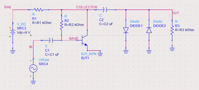
If your board does not have any of the holes connected you will have to make groupings for nodes yourself.  Finally, pick groups of holes that are near each other, but not too close, and label them as your nodes.

20180316_094536It is also a good idea at this point to sketch you components right in the board using your nodes as a reference. I like to do this on paper with a pencil because it can take a few tries to get a nice arrangement. We can see in the sketch to the left that I had trouble grounding all my parts at the output. To make this easier I connected a group of holes to the negative rail using a short wire.

Step 2: Test Your Circuit (optional but recommended)

20180315_123121It is always a good idea to test a circuit before soldering it together. Testing can be difficult without expensive lab equipment which is why I have made this step optional. Start by putting your parts on a breadboard in accordance to your sketches.

20180315_123235

Power Supply Unit – PSU (upper) and Variable Signal Generator – VSG (lower)

In the circuit diagram, there is an AC source called ‘VtSine’. This source will be your guitar, but for testing purposed we can use a Variable Signal Generator. V_DC will be a 9V battery but again, for testing purposes we can use any DC PSU. To measure hook up an oscilloscope with one probe across the input from the Signal Generator and the second probe across R3.

Below we can see the input in yellow, a nice clean guitar signal, and the output in green. The output is not only amplified to be louder, but we have also turned that nice smooth sine wave into an asymmetric square wave. Square waves have a much dirtier tone than sine waves due to the rapid change from + to -.

20180315_123046

With good test results, you are ready to complete your creation!

Step 3: Solder The Board (also optional)

20180316_203644If you skipped the last step, soldering might not appeal to you either but rest assured as it is not completely necessary. You can leave your pedal completely exposed on a breadboard if you wish. You will simply need to replace the VSG with a 1/4” Jack and the PSU with a 9V battery snap. The other 1/4” Jack will go in parallel with the diodes and R3. Take a look at my circuit if you’re having trouble and try to draw it out. I used green wire for guitar and auburn for amp. Mapping these circuits can be difficult so its a good idea to try to match the configuration you had on the breadboard. At this point you should only solder the parts on the board. Leave loose wires in place of the guitar input, amp output, and battery.

Step 4: Put It In A Box

20180316_203319
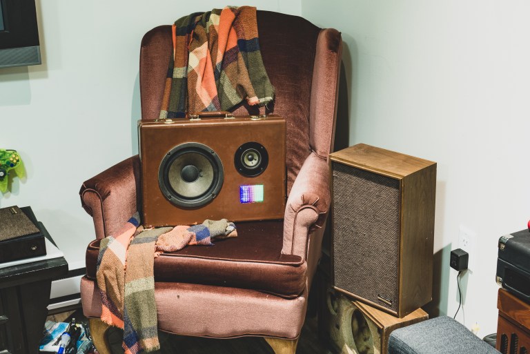
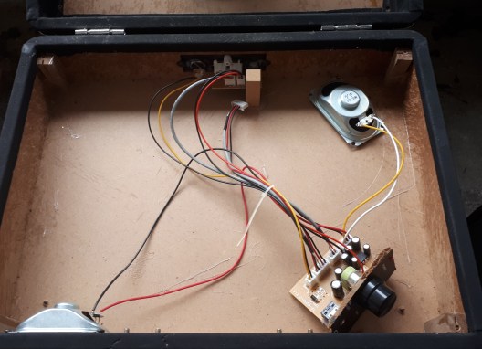
To keep everything safe it is a good idea to put your guitar pedal in a box. I put mine in a old bell box with a button on it. If you put a button in your pedal you will need to connect either end of it to the two positive parts of the 1/4” jacks. The positive parts are the ones that make connection with the patch cable. 20180316_210124The button will allow you to toggle on bypass by creating a short from input to output. Make sure to place your board in the box and feed your loose wires through the appropriate holes before soldering the button, battery, or 1/4” jacks. Finish it off by pulling the excess wire into the box and fastening the jacks and button in place.

Step 5: Rock Out

You’re ready to rock! Plug your guitar  in and unleash the power of The Stephen ROCKing Pedal. If you have any trouble with this build, please don’t hesitate to leave a comment or reach out to me through the contact page.

20180316_203208


Continue reading

Basement Builds #1: Tin Can Mic

Hello and welcome to the first instalment of  Basement Builds! In this series, I will be showing you how to make various electronics. As a musician, I like to focus my builds on audio equipment but I will occasionally branch out if I feel I have something interesting to show or a special request. I would like these Basement Builds to be as accessible as possible so I will focus on keeping them as simple and low-cost as I can.

To start off the series I wanted to recreate my first ever project which was making a Tin Can Microphone. My primary motivation behind this build was to be able to sing along with my guitar without buying too much extra stuff. I already had a guitar amp so did not want to buy a microphone amp as well. I also liked the idea of not having to carry around two amplifiers. An XLR to quarter-inch adapter would have allowed me to send a regular old microphone through my guitar amp but this did not appeal to the engineer in me.  I will not be going into too much technical detail with this series and keeping it centered around the build itself but I do encourage you to look more into the theory if you are interested. With all that being said, let’s get started!

Step 0: Gather Required Materials

labeled
For this build, you will need a few things; most of which you will probably already have at home and the others I will include links for.

  • Tin Can
  • A Thin Sock
  • Soldering Gun (or iron)
  • Solder
  • Flux (optional)
  • Wire (unless your piezo pip already has leads on it)
  • 1/4” Barrel Jack
  • Piezo Pickup

With all of your materials gathered, we are ready to begin.

Step 1: Prepare Your Can

20180303_153700 
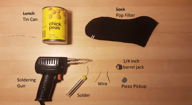
The first thing you will have to do is get the can ready to act as the housing for your microphone. You can use any can that you like but I recommend choosing a sturdy can that fits well in your hand or gig bag. Once you have emptied and cleaned your can you need to pierce a hole in the side or bottom. I chose the side so the mic could be set down while in use.  The hole will have to be just large enough for the end of the barrel jack to stick through snugly. Be careful not to make the hole too large or you will have trouble getting the jack to stay.

Step 2: Soldering

With the housing ready to go, it’s time to connect the innards of your microphone. I chose to solder my parts together to increase the durability of my build but electrical tape can work in a pinch. If you are new to soldering I recommend you head over to youtube and watch some tutorials before going any further. Also remember to always wear safety goggles and do your soldering in a well-ventilated area.

Step 2.1: Attaching leads to your pickup

20180303_160552
For this build, I only used parts found in my basement so this step may be unnecessary for you. Most Piezo Pickups already have leads attached to them but I pulled this one out of an old McDonald’s toy (I think) and the leads came off. To put new leads on a Piezo Pickup simply solder two wires to the bottom of it.  One wire will need to be attached to the outer ring and the other wire to the inner circle. These correspond to the positive and negative parts of the pickup. Using a bit of flux and leaded solder will help you get a much cleaner finish than I was able to.

Step 2.2: Attaching your pickup to the barrel jack

20180303_160636 With leads on your pickup, it is ready to be attached to the barrel jack. You will need to affix the two leads from the pickup to the two wings on the barrel jack. It should not matter which lead goes on which wing so long as you attach one to each. If you are not comfortable with soldering this step can be done without so long as you got a pickup with leads and skipped the last step. Simply feed the wire through the hole, fold it back, and give it a little twist. 20180303_161041 Those of you conformable with soldering should add a little bit here to increase the durability of the connection. Finally wrap the connection in electrical tape or shrink-wrap to finish it off an avoid shorts.

Step 3: Putting It All Together

20180303_161317Now all of the components are ready to go and the final step is assembling your microphone. This part can be a bit tricky if you have big hands like me and cannot get them inside your can. Needle nose pliers can be quite helpful here. First, take one nut and the washer off of your barrel jack. Then feed the end through the hole in the can and fasten the washer and nut back on the jack from the outside of the can. This should hold the jack firmly in place. Next, using a piece of double-sided tape (or any adhesive of your choosing) secure the pickup to the bottom of the can. Finally, stuff the thin sock into the can, toe end first, and fold the top down over the rim of the can. This will not only cover the possible sharp edge but also act as a pop filter for better sound quality.

Step 4: Rock Out!

Rockstar

20180303_161454

You’re done! There’s nothing left to do now but clean up your workstation and have fun playing with your very own microphone. My personal favorite thing to do with this Tin Can Microphone is to experiment passing it through guitar pedals. Since we used a 1/4” barrel jack rather than an XLR you can use your guitar patch chords to send this mic directly to your pedals. Throw some distortion of your voice, or delay, or maybe even send it into a loop pedal synced with your guitar to really kick things up a notch. I hope you have enjoyed this tutorial, please leave a comment and stay tuned for the next Basement Build!