Hello and welcome back to Basement Builds! In this installment, I will be showing you how to make your very own Distortion Guitar Pedal. I like to call this pedal The Stephen Hawk ROCKing Pedal (may he rest in peace) because it’ll kick your tone into high gear and have you tearing through the fabric of space and time.  I have designed this pedal to be as simple as possible with very few parts so you don’t need to be a world-class physicist to put it together.
Step 0: Gather Required Materials
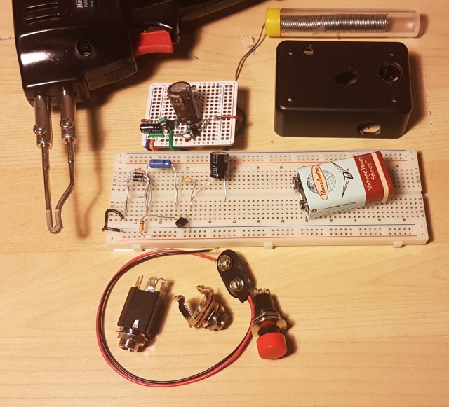 The first thing you will need to do is gather your parts. As with the microphone, most of these parts can be found in your home but I will try to link as much as possible to be safe.
- Resistors x3
- Capacitors x2
- Diodes x2
- Transistor
- Soldering Gun (or iron)
- Solder
- Flux (optional)
- Wire
- Breadboard or Perfboard
- 1/4” Barrel Jack x2
- 9V Battery Snap (or 12V barrel jack)
- Bell Box (optional)
Resistors and capacitors have a large effect on the circuit’s output so it is important to choose carefully. The transistor and diodes are also crucial to the pedal’s performance but any NPN BJT and regular diodes will work fine. I handpicked all of my values to produce my own unique tone but if you can’t find the same values I also used ADS to simulate the circuit and found a good range for each component.
| Part | Min | Mine | Max |
|---|---|---|---|
| C1 | 0.1 uF | 4.7 uF | 100 uF |
| C2 | 1 uF | 1 uF | 100 uF |
| R1 | 1 kOhm | 9.84 kOhm | 20 kOhm |
| R2 | 2 kOhm | 98.2 kOhm | 1 MOhm |
| R3 | 1 kOhm | 98.4 kOhm | 1 MOhm |
For R1 you should try to stay as close to 10 k as possible. C2 and R3 are much less important as long as you stay within my range. C1 and R2 are where this gets exciting. C1 is used primarily to block the DC voltage from going back into your guitar but it also has some control over the tone. A lower value for this capacitor cuts more bass so keep that in mind when choosing your cap. This could also be replaced with a variable capacitor to give your pedal a tone knob. R2 is used to bias the transistor which controls the gain of the pedal. More resistance here leads to more gain at the output. A variable resistor, or potentiometer, here can act as a volume knob.
Step 1: Plan Your Layout
Before you begin soldering any connections it is very important to plan how you are going to construct your circuit. Every breadboard/perfboard is different so I can’t tell you exactly how to hook it up but I do have some guidelines.
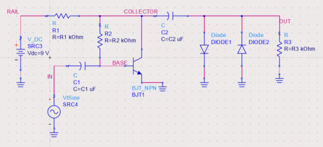
I like to start by looking at the full circuit diagram and labeling nodes. A node is where two or more components meet. In the figure below I have labeled the nodes RAIL, IN, BASE, COLLECTOR, and OUT. Since there are five nodes, there will be five points of connection to consider.

I then count the number of connections on each node to see how they will fit on my board. We can see that node OUT has four components, five including the jack not shown on the diagram, which is a lot for smaller boards. If you have a board where the holes are connected in three’s or four’s, you will need to connect two grouping together with a short wire or touch of solder to give yourself more space.  If your board does not have any of the holes connected you will have to make groupings for nodes yourself. Finally, pick groups of holes that are near each other, but not too close, and label them as your nodes.
 It is also a good idea at this point to sketch you components right in the board using your nodes as a reference. I like to do this on paper with a pencil because it can take a few tries to get a nice arrangement. We can see in the sketch to the left that I had trouble grounding all my parts at the output. To make this easier I connected a group of holes to the negative rail using a short wire.
Step 2: Test Your Circuit (optional but recommended)
 It is always a good idea to test a circuit before soldering it together. Testing can be difficult without expensive lab equipment which is why I have made this step optional. Start by putting your parts on a breadboard in accordance to your sketches.

Power Supply Unit – PSU (upper) and Variable Signal Generator – VSG (lower)
In the circuit diagram, there is an AC source called ‘VtSine’. This source will be your guitar, but for testing purposed we can use a Variable Signal Generator. V_DC will be a 9V battery but again, for testing purposes we can use any DC PSU. To measure hook up an oscilloscope with one probe across the input from the Signal Generator and the second probe across R3.
Below we can see the input in yellow, a nice clean guitar signal, and the output in green. The output is not only amplified to be louder, but we have also turned that nice smooth sine wave into an asymmetric square wave. Square waves have a much dirtier tone than sine waves due to the rapid change from + to -.

With good test results, you are ready to complete your creation!
Step 3: Solder The Board (also optional)
 If you skipped the last step, soldering might not appeal to you either but rest assured as it is not completely necessary. You can leave your pedal completely exposed on a breadboard if you wish. You will simply need to replace the VSG with a 1/4” Jack and the PSU with a 9V battery snap. The other 1/4” Jack will go in parallel with the diodes and R3. Take a look at my circuit if you’re having trouble and try to draw it out. I used green wire for guitar and auburn for amp. Mapping these circuits can be difficult so its a good idea to try to match the configuration you had on the breadboard. At this point you should only solder the parts on the board. Leave loose wires in place of the guitar input, amp output, and battery.
Step 4: Put It In A Box
 To keep everything safe it is a good idea to put your guitar pedal in a box. I put mine in a old bell box with a button on it. If you put a button in your pedal you will need to connect either end of it to the two positive parts of the 1/4” jacks. The positive parts are the ones that make connection with the patch cable.
  The button will allow you to toggle on bypass by creating a short from input to output. Make sure to place your board in the box and feed your loose wires through the appropriate holes before soldering the button, battery, or 1/4” jacks. Finish it off by pulling the excess wire into the box and fastening the jacks and button in place.
Step 5: Rock Out
You’re ready to rock! Plug your guitar in and unleash the power of The Stephen ROCKing Pedal. If you have any trouble with this build, please don’t hesitate to leave a comment or reach out to me through the contact page.

P.S. How Does It Work?
This entire build is possible because of the transistor. Transistors are able to do a lot of things based on their type and mode. The transistor we are using is a Bipolar Junction Transistor in a Common Emitter configuration which is operating in Forward-Active mode. Basically all that means is it’ll work as an amplifier for us.
R1 and R2 are part of the biasing network for the transistor. The biasing network is used to control the voltages at the collector and base, keeping the transistor in Forward-Active mode. The battery supplies the transistor with power allowing it to amplify the input.
C1 and C2 are coupling capacitors which are used to block DC signals while allowing AC to pass. This keeps the power inside the pedal and away from the in or outputs.
Last but certainly not least are the two diodes. Diodes allow current to flow through one way and not the other. Having two diodes anti-parallel at the output will clip the top and bottom of the waveform resulting in the square shape.
Useful Links:
Handy tool for determining Resistor Values
Fantastic guide on different types of distortion and how to achieve it
